Bus and bushing covers
Insulator covers and bus connection cover-ups (GPFIC)
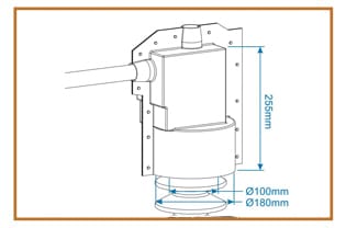
A GPS 1099 cover is 255 mm tall over a Ø180 mm base, with a 100 mm hole moulded into the bottom face and nothing else open.
GPFIC bus and bushing connection insulating covers
Pre-formed polyolefin covers that go over an assembled connection at a substation: a breaker bushing, a standoff insulator, a capacitor head, a regulator terminal. Twenty codes are printed on the manufacturer's sheet and they differ in one thing, which is where the moulding already has a hole in it. The rest are cut on site, and the cover is published as re-enterable, so the connection under it can be re-torqued or thermally surveyed years later without buying it again.
- Arrives in the shape of the connection, so nothing is built up out of tape or sheet at height
- Twenty standard codes, with in-house tooling and a die shop behind anything outside them
- Design assistance and CAD drawings offered for shapes the chart does not carry
- Reuse after a maintenance visit is the commercial argument the sheet makes for the range
| Material | High-quality polyolefin, UV stable and track resistant |
|---|---|
| Published codes | GPS 1070 through GPS 1214, twenty in all |
| The four common patterns | GPS 1099, GPS 1178, GPS 1167, GPS 1165 |
| Goes over | Circuit-breaker bushings, bus standoff insulators, capacitors, transformer bushings, voltage regulators, potential transformers |
| Openings | Moulded in on most codes; trimmed to size on site at entry and exit |
| Comes off | Yes. Published as re-enterable for other maintenance needs, then reused |
| Range standard | ANSI C37.20.2, stated for the Insulation Enhancement range |
No property table is published for the GPFIC cover itself
The Insulation Enhancement Products sheet carries three technical specification tables and not one of them belongs to these covers. They sit against the polyolefin line cover, the overhead line tube and the silicone line cover, which are separate products further forward in the same PDF. For the connection covers the material is given as high-quality polyolefin, UV stable and track resistant, and ANSI C37.20.2 is quoted for the range rather than for a code. So if a submission needs a dielectric strength, a temperature limit or a tracking result against a GPS number, ask the manufacturer for it against that number. Do not lift the 20 kV/mm and −45 to +105 °C figures printed a few pages earlier, because those were measured on the line-cover compound.
The four patterns most connections land on
| Gala code | Moulded opening | Dimensions on the drawing | Cut on site? |
|---|---|---|---|
| GPS 1099 | 100 mm on the bottom side | 255 mm tall; Ø100 mm and Ø180 mm at the base | Entry and exit holes only |
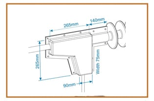
| GPS 1178 | 40 mm on the left and bottom sides | 265 mm and 265 mm across the body; 140 mm arm; 75 mm wide; 90 mm at the bottom | Entry and exit holes only |
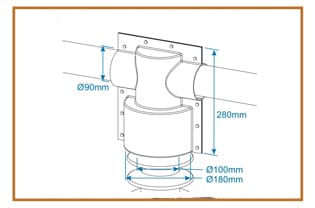
| GPS 1167 | 90 mm left and right, 100 mm on the bottom | 280 mm tall; Ø90 mm each side; Ø100 mm and Ø180 mm at the base | Entry and exit holes only |
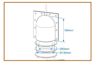
| GPS 1165 | None | 164 mm tall; Ø90 mm and Ø130 mm | Yes. The conductor side is field cut |
Openings and dimensions exactly as printed on the manufacturer's Insulation Enhancement Products sheet. The drawings do not dimension the same feature on every code, so open the sheet before any figure here goes into a clearance calculation.
Pick the pattern by the geometry, not by the asset name
What the asset register calls the item decides nothing. Two standoffs on the same gantry take different covers if one carries a bus straight through and the other has a jumper dropping away underneath. Count the directions metal leaves the connection, then count the directions the moulding is already open, and the code falls out of that.
One entry and an insulator stack below it is GPS 1099, open 100 mm at the bottom and nowhere else. Metal leaving to the left and downwards from a narrower body is GPS 1178, with its two 40 mm openings. Bus running straight through, entering and leaving on the same axis with the insulator underneath, is GPS 1167, open 90 mm on each side and 100 mm at the base. GPS 1165 is the small one that arrives closed all round, 164 mm tall, for the case where nothing standard matches and the fitter decides where the conductor passes.
Trimming is the design, not a concession. The holes are opened out to the dimension of whatever passes through them, which is how one code covers connections a drawing office would treat as three jobs. It also means an oversized cut is the one part of the fit nobody can put back.
The rest of the published GPS range
| Gala code | Moulded opening | Dimensions on the drawing |
|---|---|---|
| GPS 1070 | 116 mm on the bottom side | 215 mm; Ø128 mm |
| GPS 1102 | 35 mm on the conductor side | 195 mm; 110 mm; 110 mm |
| GPS 1137 | 35 mm on the conductor side | 90 mm; Ø115 mm |
| GPS 1158 | 50 × 10 mm on the busbar side | 86 mm; Ø60 mm |
| GPS 1160 | None, field cut | H 400 mm, L 450 mm, W 250 mm |
| GPS 1161 | None, field cut | H 600 mm, L 450 mm, W 250 mm |
| GPS 1162 | 90 mm on the conductor side | 200 mm; 175 mm; 135 mm |
| GPS 1163 | 90 mm left and right, 60 mm on the bottom | 275 mm; Ø90 mm; Ø60 mm |
| GPS 1164 | 90 mm on the conductor side | 200 mm; 175 mm; 135 mm |
| GPS 1166 / GPS 1196 | None, field cut on the conductor side | 475 mm / 390 mm tall; Ø220 mm / 175 mm; Ø140 mm / 100 mm |
| GPS 1197 | 50 mm on the conductor side, 125 mm on the bottom | 100 mm; 50 mm; Ø125 mm |
| GPS 1211 | 35 mm on the bottom; conductor side field cut | 227 mm; 97 mm; 40 mm; Ø55 mm |
| GPS 1212 | 40 mm on the bottom; conductor side field cut | 488 mm; 318 mm; 200 mm; Ø203 mm; Ø140 mm; Ø114 mm |
| GPS 1213 | None, field cut | Not dimensioned on the sheet |
| GPS 1214 | High-voltage insulator protection cover | 600 mm diameter |
Sixteen further codes from the same sheet. Between this table and the one above, every GPS code the manufacturer publishes is listed.
The assets this range is sized for
Taken from the manufacturer's own list for the GPFIC covers, in the order the sheet gives them:
- Circuit-breaker bushings. The porcelain stack plus the terminal pad on top of it, which is where a bird lands and where a jumper swings.
- Bus standoff insulators. The commonest case, and the one the GPS 1099 and GPS 1167 drawings are both built around.
- Capacitors. Bank terminals sitting close together on a rack, where the exposed metal is small and the phase spacing is fixed by the frame.
- Transformer bushings. Distinct from a switchgear bushing boot, which is a cable-side part and is not published here.
- Voltage regulators and potential transformers. Pole and pad assets whose terminal geometry rarely matches anything drawn, and where GPS 1165 or GPS 1213 arriving closed is the practical answer.
The insulator itself, as opposed to the connection on top of it
Two codes on the sheet cover the insulator rather than the metal. GPS 1214 is a 600 mm diameter pre-formed cover whose published job is protecting a high-voltage insulator from the damage caused by bird excretion, which is a pollution and flashover problem rather than a bridging one. GHCE 1 is a different thing again, a wraparound creepage extender at 564 mm outer diameter over 430 mm and 372 mm inner rings, and it adds creepage path to a string instead of covering a connection.
The two solve different faults, and a search for an insulator cover returns both. Birds bridging phase to earth is a connection cover from the tables above. A flashover in the first rain after a dry spell is a surface problem, and an extender or a shed cover is the part being looked for.
Cover-up, cover up, safety cover-up: one part, three spellings
North American utility crews call these cover-ups, and the word travels badly. Two engineers describing the same 265 mm moulding will type it three ways, none of them what the sheet prints, which is Bus Connection Insulating Cover. Pull-on field protection cover is a fourth name for the same family, and an empty catalogue search usually has no other cause.
The word does carry one real distinction worth keeping. In North American usage a cover-up is temporary line protection a crew puts up to work near something and takes down at the end of the shift. The parts on this page are not that. They are fitted to stay, and the re-entry the sheet describes is a maintenance operation on a de-energised connection, not a rubber goods routine.
The four common patterns, as the manufacturer dimensions them
When none of the twenty codes fits: the Insulshroud route
A recloser head, an odd clamp or a retrofitted terminal arrangement matches no pattern, and trimming a standard cover further does not make it fit. The manufacturer's answer there is Insulshroud, a flexible PVC boot moulded to size, shape and quantity, backed by an in-house tool and die shop, a formulation lab and electrical testing in the same works.
It buys differently from a GPS code. It ships complete with its fasteners, so it is installed, removed and replaced as an assembly rather than cut. Stock colours are grey, red and black. Its page cites UL File No. E335936, the same number the company record gives for Busboot and Bustube, so read it as a listing across the moulded shroud family rather than a certificate against one drawing.
The split is a quantity question. One or two odd connections are usually cheaper covered by a closed code like GPS 1165 or GPS 1213, cut to suit. Twenty bays carrying the same recloser is where a moulding pays for its tool.
What this does not do
A pre-formed cover fits a pattern, not a drawing.
- It does not make the connection safe to touch. A cover-up over a live bushing is insulation enhancement against a bird, a branch or a swinging jumper, and it changes nothing about the isolation, earthing or approach rules that applied yesterday.
- It carries no published voltage class. The line covers in the same PDF are given at 66 kV and 765 kV; the GPS connection covers are given no kV figure at all, so a code picked off the tables above has been picked on geometry and nothing else.
- It is not a sealed enclosure. No ingress-protection rating appears on the sheet, and GPS 1165 arriving with no opening is a moulding decision rather than a seal.
- It is not a bushing boot. That part sits on the cable side of a switchgear or transformer bushing, and it is published on 66kvcabletermination.com, a sister property run by the same operator as this site: bushing boots.
- Re-entry is published, but not counted. The sheet gives no number of re-fits and no re-inspection interval, so a cover coming off for the third time deserves a look at its trimmed edges before it goes back on.
- It does not stretch to a body 100 mm too small. That is the switchgear shroud case or the moulding case, not a knife case.
Where to go from here
- Fitting covers, shrouds and caps: four procedures and one removalThe trimming sequence, and the one part of this range that comes off again.
- Insulating shrouds: the removable cover over an assembled connectionThe indoor equivalent, where the connection is inside a panel.
- Wildlife protection covers for distribution and substation assetsThe outage these covers were published to stop, asset by asset.
- How to read an insulating cover datasheetIncluding which table on a multi-product sheet belongs to which part.
- Electrical insulation covers, indexed by where the bare metal isPart of: the full index of covered objects.
Send the connection, not the code
Twenty patterns is a lot to guess from, and the wrong guess is discovered at height. Four facts settle it: how many directions metal leaves the connection, the diameter of each, the height from flange to terminal top, and whether the asset is a breaker, a standoff, a capacitor or a regulator. The manufacturer's own page for the range is Overhead Line Covers and Bus Connection Insulating Covers.